Precise sheet metal part drawings are essential for efficient manufacturing. It is crucial for designers to prioritize DFM, master flat patterns, and pay attention to bending-specific design. Clear communication with manufacturers is crucial to streamline production and avoid costly errors.
Sheet metal part drawings are the fabricator’s guide, detailing each step in creating components. Precise and clear drawings ensure efficient manufacturing, sheet metal part accuracy, and prevent costly errors.
Bends and complex geometries present unique challenges in sheet metal drawings. Unlike solid models, sheet metal parts deform during bending, making accurate flat patterns critical.
Complex geometries further complicate this, requiring careful consideration of sheet metal bending techniques, bend deductions, K-factors, and material thinning to ensure bend accuracy and dimensional tolerances.Tolerance allocation also requires thorough attention.Overly tight tolerances increase manufacturing complexity and costs, while loose tolerances compromise functionality.
Balancing design intent and manufacturability in sheet metal drawings demands a clear understanding of sheet metal behavior and fabrication. Here, we discuss the essential tips that will help you with this.
7 Tips for Creating Accurate Sheet Metal Part Drawings
Accurate sheet metal part drawings are vital for successful manufacturing. Here are 7 top tips to ensure your designs are precise and error-free.
Tip 1: Prioritizing Design for Manufacturability (DFM)
Sheet metal DFM is about strategically choosing materials and simplifying the design for optimal manufacturing. The right material choice impacts tooling wear, formability and product lifespan.
For example, HSLA steels offer a good strength–formability balance for structural parts, whereas aluminum alloys, although lightweight, might require specialized tooling due to their lower formability.
Keep designs simple. Minimize bends and complex features to reduce tooling costs and forming defects. Opt for simple bends over complex curves if functionality allows.
Consider sheet metal part assembly efficiency from the start. Features like tabs, slots and self-locating geometries simplify assembly and reduce fixture reliance. Ensure parts are easy to access and handle during assembly for greater efficiency.
Tip 2: Mastering the Flat Pattern Design

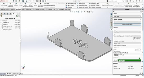
The flat pattern is the 2D blueprint that dictates how the sheet metal components will be cut and bent. It needs to be accurate, as even small discrepancies can throw off the entire sheet metal fabrication process.
Start by understanding the bend deduction. This is the material removed the poetically from the sum of the outer dimensions of a bend to arrive at the correct flat length. Different materials and bending methods require different bend deductions. Ignoring this will lead to parts that ’tfit together correctly.
Consider sheet metal grain direction, represented by an arrow in the drawing, as it impacts strength and formability. Orient parts to minimize bending across the grain to prevent cracking.
Before releasing the drawing, use CAD tools to simulate the part’s unfolding to catch errors early.
Tip 3: Paying Attention to Bending-Specific Design

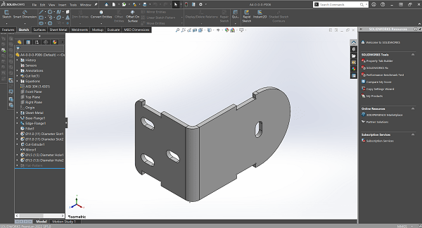
Bend features and reliefs, vital at flange intersections, prevent tearing and facilitate tool clearance. Tailor their size and shape (round, rectangular or teardrop) to the material and bend angle.
Always orient bends perpendicular to the material grain to minimize cracking, particularly in materials with pronounced grains like aluminum.
Factor in bend deductions when placing features. Account for material elongation during bending. Maintain sufficient spacing between holes, cutouts and bend lines to preserve feature integrity after forming.
Specify the appropriate bend deduction technique (bend allowance or bend deduction) to accurately determine the flat pattern’s developed length, ensuring the final part matches the intended dimensions.
Tip 4: Applying Accurate Dimensioning and Tolerances
Dimensioning and tolerancing are critical in sheet metal part drawings for conveying manufacturability and interchangeability. Neglecting to explicitly define tolerances leads to misinterpretations and unacceptable parts, especially in high-volume production environments.
To streamline the design process, establish default tolerances for the sheet metal fabrication processes typically employed. These defaults, documented in a company standard or directly within the CAD system, mitigate ambiguity by providing a baseline for manufacturing.
For instance, specifying a general tolerance of ±0.010 for non-critical dimensions allows for efficient production while reserving tighter tolerances, like ±0.005, for features demanding higher precision.
This practice minimizes clutter on drawings and clearly communicates design intent by highlighting only those dimensions requiring special attention.
Tip 5: Including Complete and Essential Information
A sheet metal drawing that solely conveys dimensions leaves much open to interpretation. For example, missing annotations on a bend radius could lead to costly rework if the fabricator’s default approach differs from the design intent.
To eliminate ambiguity and ensure the fabricated part aligns with your vision, you need to incorporate material properties specifications, surface finish requirements (e.g., “125 Ra max” for surface roughness), heat treatment details, and inspection criteria.
Thisrequires a comprehensive checklist:

Tip 6: Choosing the Right File Formats
To streamline collaboration and production, select the right file format for your sheet metal drawings.
- DXF, an open vector format, ensures compatibility across CAD platforms and is ideal for exporting 2D designs, especially flat patterns for laser cutting and CNC punching.
- DWG, while specific to AutoCAD, is widely used in CAD for both 2D and 3D designs. Export your sheet metal designs with bend information and annotations for various manufacturing processes.
- STEP, a neutral format, allows seamless data exchange between CAD systems, preserving both geometric and manufacturing data,like bend tables and material specifications.
Always follow the best practices for efficient sheet metal modeling in CAD tools like SolidWorks. Retain a copy of your work in your native CAD format to preserve design history, parameters and features, simplifying future edits.
Tip 7: Conducting a Thorough Quality Assessment
Thoroughly assess the quality of your sheet metal part drawings before being released to manufacturing. Implement a systematic drawing review process to insure completeness, clarity and adherence to design intent. Accurate drawings provide the reference for sheet metal part inspection during manufacturing quality checks.
Target key aspects, such as hole/feature placement accuracy, correct representation of flat patterns and bend details, and proper material selection with consideration for grain direction.
Utilize a structured checklist during the quality assessment to maintain consistency and minimize errors. Leverage software tools, like SOLIDWORKS Inspection, for automated verification of dimensional accuracy, GD&T compliance, and potential manufacturability issues.
This approach helps reduce costly rework and production delays and enhances the overall quality and efficiency of your sheet metal fabrication process.
Case Study:

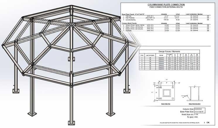
TrueCADD reduced design iterations by 50% for a U.S.-based steel shelter manufacturer by providing comprehensive design drafting support. The project involved creating over 1,800 SolidWorks 3D models and part drawings, including detailed manufacturing and assembly drawings with BOMs, ensuring efficient production workflows.
Benefits of Proper Collaboration and Communication During the Sheet Metal Design Process
Early engagement with manufacturing experts during the design phase ensures the sheet metal part design is feasible for fabrication. This avoids costly reworks and production delays. Open and transparent communication between designers and manufacturers using 3D models, 2D drawings, and digital annotations streamlines design revisions and approvals.
Clear and concise annotations, such as bend notes, directly on the 2D drawing showing bend deductions, K-factors, and bend radii, are crucial for conveying manufacturing instructions.
Accurately documenting sheet metal manufacturing techniques like bending, punching, and laser cutting using proper GD&T callouts and tolerances on the drawings is essential for achieving the desired part functionality and quality.
Wrapping Up
Creating sheet metal part drawings is a fundamental skill for designers and engineers in manufacturing. By understanding key design considerations, you improve communication with manufacturers, reduce errors and rework that leads to faster turnaround times and cost savings.
A well-crafted drawing is the blueprint for bringing your designs to life. It ensures successful production and helps you gain a competitive edge in the sheet metal market.